Difference between revisions of "DPH.IP Doorphone connection"
From pubWiki-en
| (One intermediate revision by the same user not shown) | |||
| Line 17: | Line 17: | ||
|STA | |STA | ||
|- | |- | ||
| − | |AC ||rowspan="2"| power supply connections | + | |AC ||rowspan="2"| power supply connections 24 - 48VDC |
|- | |- | ||
|AC | |AC | ||
| Line 33: | Line 33: | ||
Connection scheme of doorphone DPH.IP-CR0RF is presented on following figures.<br> | Connection scheme of doorphone DPH.IP-CR0RF is presented on following figures.<br> | ||
<center>[[File:DPH.IP-CR0RF_connection1.png|500px]] or [[File:DPH.IP-CR0RF_connection2.png|500px]]</center><br> | <center>[[File:DPH.IP-CR0RF_connection1.png|500px]] or [[File:DPH.IP-CR0RF_connection2.png|500px]]</center><br> | ||
| − | |||
| − | |||
| − | |||
Latest revision as of 08:27, 13 October 2017
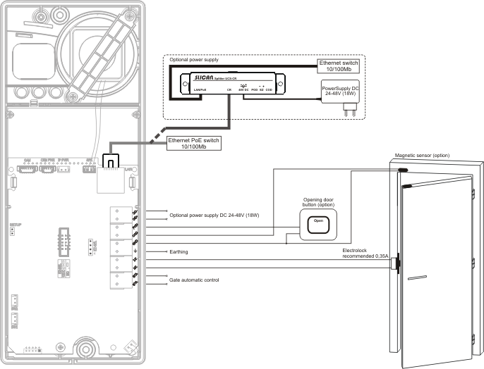
Connecting doorphone can be executed via appropriate cables connected to connecting terminal located on doorphone PCB. Connecting terminal is visible and accessible afer unscrewing front panel, this operation is described in chapter DPH - Opening doorphone casing.
|
Connections located in connection terminal, usetd to doorphone installation are presented in following table:
Connection scheme of doorphone DPH.IP-KSxx.C is presented on following figure.

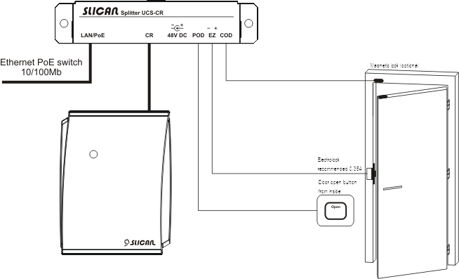
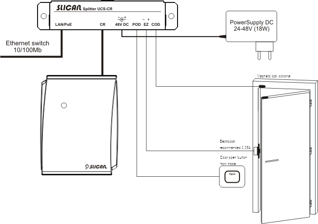
Connection scheme of doorphone DPH.IP-CR0RF is presented on following figures.
 or
or 
