DPH.IP Doorphone connection

From pubWiki-en
Revision as of 08:27, 13 October 2017 by Grzegorzz (Talk | contribs)

(diff) ← Older revision | Latest revision (diff) | Newer revision → (diff)
Jump to: navigation, search

Connecting doorphone can be executed via appropriate cables connected to connecting terminal located on doorphone PCB. Connecting terminal is visible and accessible afer unscrewing front panel, this operation is described in chapter DPH - Opening doorphone casing.

Warning! Before connecting cables to connecting terminal, cables should be bring into the casing via hole located on casing backside.

Connections located in connection terminal, usetd to doorphone installation are presented in following table:

Ikona uziemiena biała.PNG earthing (for proper operation of doorphone over-voltage protection)
LAN RJ45 socket for LAN cable (PoE support)
EZ electrolock, 12V DC, max 0.7A
EZ
STA isolated normaly open relay connection used to control additional device - allowable voltage is equal to max 24V AC STA Max 0.7A
STA
AC power supply connections 24 - 48VDC
AC
COD opening door sensor - disconnection from GND decrease EZ relay operation time
POD opening door button (relative to GND)
GND ground for POD, COD signals

Connection scheme of doorphone DPH.IP-KSxx.C is presented on following figure.
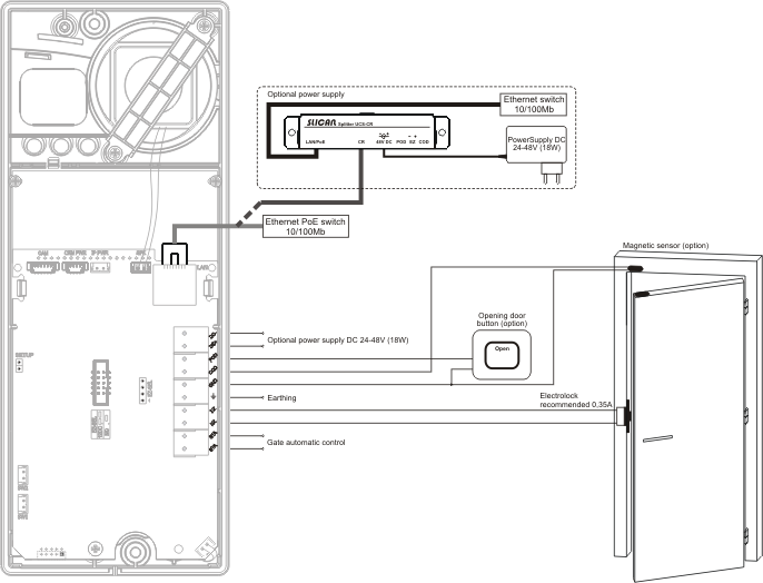
DPH.IP-KSxxRF sch podlaczenia eng.png

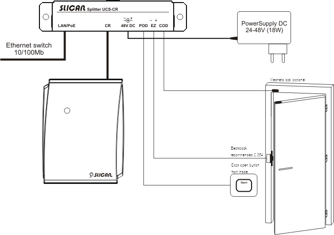
Connection scheme of doorphone DPH.IP-CR0RF is presented on following figures.
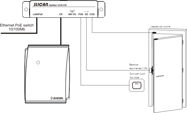
DPH.IP-CR0RF connection1.png or DPH.IP-CR0RF connection2.png